|
Latest News
MAP Sensors (Manifold Absolute Pressure)
The Manifold Absolute Pressure Sensor (MAP sensor) measures inlet manifold pressure indicating engine load. The output signal from the MAP sensor and the air temperature sensor are required by the ECU to calculate intake air mass. The signals sent to the ECU is used as one input to determine fuel delivery and ignition timing. Map sensors were generally used on vehicles without a Mass Airflow Sensor (MAF), however on some later vehicles both MAP and MAF sensors have been fitted for more accurate monitoring of EGR operation.
Map Sensor Locations
- 1. Remotely mounted, often on the fire wall on older vehicles. Connected to the inlet manifold via a vacuum hose.
- 2. Fitted directly into the inlet manifold.
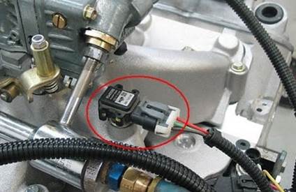
Image source: grimmermotors.co.nz
- 3. Some European vehicles included the MAP sensor in the ECU. While this eliminates the wiring a vacuum line still needs to be connect to the inlet manifold.
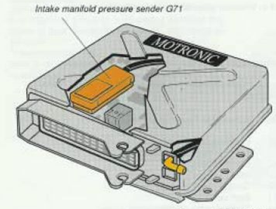
Image source: quattroworld.com
Operation
A MAP sensor is connected to the inlet manifold to measure manifold absolute pressure. They can produce an analogue or digital output. The standard MAP sensor fitted to a non-turbo charged and non-supercharged engine is a 1 Bar MAP sensor. On a turbo charged or super charged engine the manifold pressure will at times be higher than 1 Bar. Depending on boost pressure developed, these engines will be equipped with MAP sensors capable of measuring 2, 3 or 4 Bar. Many MAP sensors will include an Intake Air Temperature sensor (IAT) which is used by the ECM to monitor the temperature of the air coming into the engine.
Analogue
The analogue MAP sensor has a “Piezo Resistive Circuit” that produces an output voltage that varies proportionally to inlet manifold pressure. Manufacturer specifications must always be checked but the chart below is typical on a normally aspirated engine.
Source: ozhonda.com
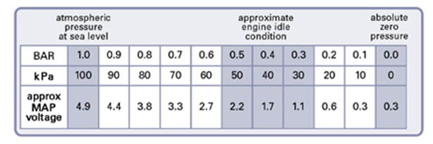
Source: fastfieros.com
Digital
The Digital MAP sensor produces a frequency that varies with manifold pressure. The ECM processes this changing frequency with the use of other input signals as engine load.
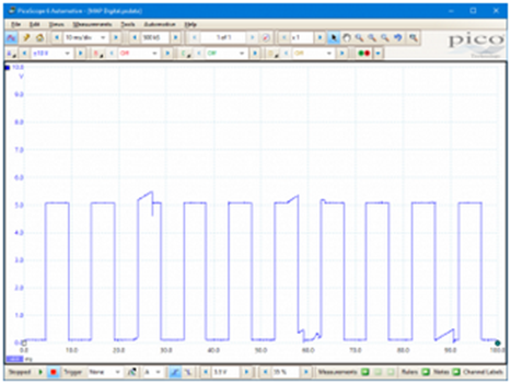
Source: picoauto.com
Testing
Most technicians will start a diagnostic procedure by extracting diagnostic trouble codes (DTC) using a scan tool. Typical MAP sensor codes include but are not limited to:
- P0105 – Manifold Absolute Pressure/Barometric Pressure Circuit Malfunction
- P0106 - Manifold Absolute Pressure/Barometric Pressure Circuit Range/Performance Problem
- P0107 - Manifold Absolute Pressure/Barometric Pressure Circuit Low Input
- P0108 - Manifold Absolute Pressure/Barometric Pressure Circuit High Input
- P0109 - Manifold Absolute Pressure/Barometric Pressure Circuit Intermittent
It must not be assumed that if a MAP sensor DTC is retrieved that the MAP sensor needs to be replaced. Further test must be performed to confirm the fault. Thorough testing of the MAP sensor Electrical Wiring Circuit and Inlet Manifold Vacuum is necessary before condemning the MAP sensor.
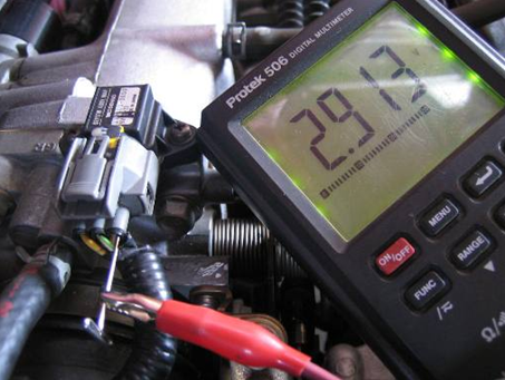
Checking the MAP sensor output using live data or graphing on a compatible scan tool at key on engine off (KOEO) condition should give a reading equivalent to 1 bar at sea level. Starting the engine and varying engine speed and load will vary this output. It is important to consult the specific vehicle manufacturer specifications to assess the results of these test.
More detailed testing information is available in a previous MAP sensor testing article at
https://premierautotrade.com.au/news/map-sensor-testing.php
The PAT Emission range includes more than 360 MAP sensors from the world’s leading manufacturers, covering over 10 million vehicles on road in Australia and New Zealand.
When you supply and fit products from PAT you can expect a product designed and tested to the vehicle manufacturer’s specifications offering OE form fit and function. |