Latest News
Accelerator Pedal Position Sensors (APPS)
What the Technician needs to know about the Accelerator pedal position sensors on a Drive by wire system.
There are generally two operating system types of APPS units that have been used utilised by manufacturers on the Link-less type – Electronic Throttle - Drive by wire system).
1. Potentiometer – contact type APS dual operating units with both output signals monitored by the ECM.
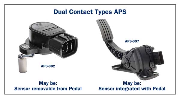
Note: The APPS is “generally” located on the accelerator pedal. This is not always the case as many vehicles utilised an accelerator cable from the pedal to operate a separately mounted APPS in the engine bay (Mercedes - early models) or integrated in the throttle body itself. (Nissan Patrol).
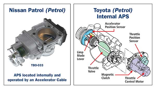
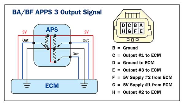
The BA/BF Falcon range utilise a triple APPS integrated in their accelerator pedal assembly. The dual or triple APPS units are required to ensure a more accurate and safer throttle operation.
2. HALL sensor- Contactless type APPS units with either analogue or PWM output signals monitored by the ECM.
These units are widely used in all vehicle types from motor vehicles to heavy trucks and plant equipment. No physical internal contact ensures a greater operating accuracy in heavy vibration and dusty conditions.
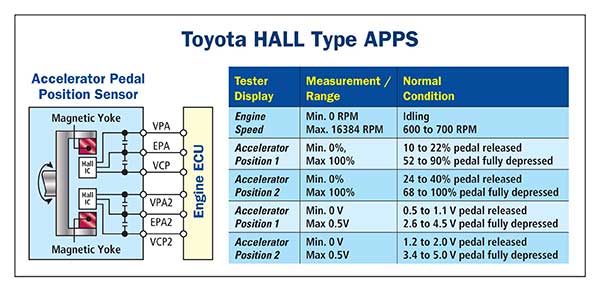
Typical Toyota dual HALL sensor APPS – Analogue output type (varying voltage).
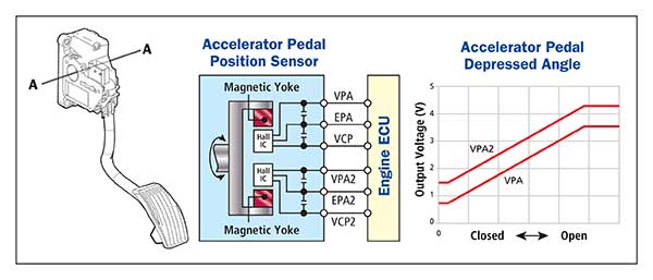
Note: Generally, the output voltages or signals will not be identical on Petrol vehicles “but” there are Diesel vehicles with identical APPS outputs. (Mazda BT-50)
What are some of the effects on a vehicle when an APPS malfunctions?
When the APPS signal/s are incorrect, the Electronic Throttle system will convert to default mode – causing:
- Check engine light on and fault code logged. Examples - P0121 Accel Pedal Sensor 1 Circuit performance / P1125 Accel Pedal Sensor.
- The throttle valve may be held in the default position, limiting engine RPM and road speed to a minimum. This is generally felt as a lack of power during acceleration. In some cases, this condition may create forced shut down and result in engine stall.
- Other systems may be affected such as transmission shifting and gear selection.
- Message displayed on dash indicating “Reduced Engine Power” – Depending on vehicle.
APPS Typical test procedures.
It is important to determine if the APPS is actually faulty, or as in many cases, external factors have created the problem. Whether a contact type or contact less type, the pre-test procedure is similar.
Are all power supplies and grounds correct? Note: Many an APPS has been renewed only to find that a power supply or ground was the cause.
Is the test equipment adequate for testing to be carried out?
- Suitable scanner
- Digital Multimeter for Voltage readings.
- Suitable oscilloscope – operational sweep (either analogue or digital signal)
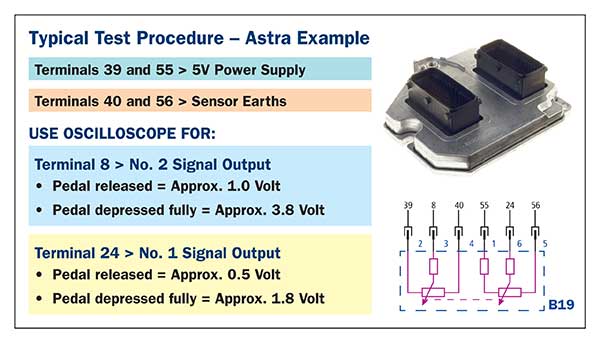
Contact type APPS test.
Contactless type APPS test.
Accelerator Pedal Released Position Learning.
Disconnecting an APPS or ECM may require an APPS pedal position relearn. Refer vehicle specifications if unsure is required for specific vehicle.
A typical Nissan procedure is:
- Ensure accelerator pedal is fully released.
- Switch IGN ON and wait for at least two seconds.
- Switch IGN OFF and wait for at least ten seconds.
- Switch IGN ON and wait for at least two seconds.
- Switch IGN OFF and wait for at least ten seconds.
The Premier Auto Trade Sensors range includes Accelerator Pedal Position Sensors that cover over 1.2 million vehicle applications in Australia and NZ.
When you supply and fit products from Premier Auto Trade you can expect a product designed and tested to the vehicle manufacturer’s specifications offering OE form, fit and function. Premier Auto Trade distributes products throughout Australia via a network of specialised resellers and leading automotive groups.
|


