Latest News
Testing Accelerator Pedal Position Sensors (APS)
What the Technician needs to know about Accelerator Pedal Position sensors during an on-vehicle diagnosis and test procedure. Typically known as an – APS / APP sensor or APPS.
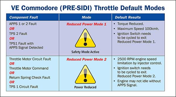
When the ECM detects a system or component fault in a “drive by wire” control system, the ECM will generally employ a specific “back up” or “fail safe” mode to ensure the vehicle can be safely moved to a destination to be repaired.
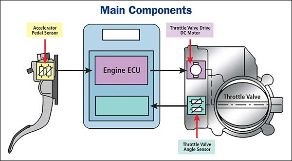
Simplified, there are 4 main components that are linked through electrical wiring that are utilised for throttle control. Each component will generally cause a variation in the failsafe driveability when a failure or out of phase condition exists.

The accelerator pedal position sensor (See APS Types and General information in our other article) may be problematic when it comes to the diagnosis procedure.
Factors that the technician must take into account during this process to ensure accuracy.
- How many output signals are expected from the APS?
This will vary depending on the vehicle system. Most APS units employ two separate output signals that are required for safety purposes and operation plausibility. Some systems may utilise 3 output signals. (Typically, BA/BF Ford Falcon). Some Diesel systems utilise a single output signal (not common)
- What type of output signal is expected from an APS?
These signals may be:
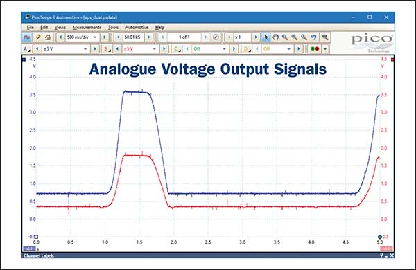
- Analogue type output voltages. (2 X APS units)

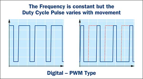
- Digital type with a varying pulse width and constant frequency (Showing a single output.)

Note: A combination of both analogue and digital PWM outputs can be found in a single APS assembly. Typically, Toyota/Lexus.
- What typical type of output readings are expected from the APS units.
(Refer to previous APS article for detailed type descriptions)
The APS output signals are generally known as APS 1 signal and APS 2 signal. (APS 3 only on a 3-output unit). The ECM uses an algorithm to validate the integrity of the signals. Most APP sensors utilise an incremental voltage value during accelerator pedal movement. The Incremental voltage of APS 2 generally represents half of the voltage of APS 1.
That is: If APS 2 displays a reading of 1.5V, the APS 1 reading would generally indicate a reading of approx. 3.0V. Even though these are typical readings, there are of course variations to these results.
- What is required if the APS output voltages / duty cycle is incorrect.
Performing the standard power supply and ground tests are essential prior to carrying out any further comprehensive testing. In many cases the APS unit has been mistakenly renewed due to incorrect diagnosis.
- Are there post fitting procedures for APP sensors?
There are vehicle systems that require a relearn procedure after the APP sensor has been renewed or disconnected. (Typically, Nissan vehicles). Refer to manufactures specifications for any post fitting procedures to ensure the vehicle is functioning correctly when it leaves your workshop.
Typical example of default mode.

The Premier Auto Trade Sensors range includes Accelerator Pedal Position Sensors that cover over 1.2 million vehicle applications in Australia and NZ.
When you supply and fit products from Premier Auto Trade you can expect a product designed and tested to the vehicle manufacturer’s specifications offering OE form, fit and function. Premier Auto Trade distributes products throughout Australia via a network of specialised resellers and leading automotive groups. |


