Latest
News
Testing EGR Systems (Exhaust Gas Recirculation) - Pt 2
September 2012
With the variety of EGR systems used for the control of
NOx emissions it is important to understand the
components operation, prior to carrying out any diagnostic
or testing. (Refer to previous issues for EGR system
operation).
Testing times for EGR systems
A defective component in the EGR system may have a
very detrimental effect to the engine performance and
therefore the emissions.
Strict emission laws and the malfunction indicator light
generally illuminated when a system fault exists, require a
prompt resolution.
1. Pneumatic EGR Valve System Component Tests
Note that vacuum supply to all components must be tested
on the vehicle to eliminate misdiagnosis
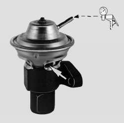
Single diaphragm type EGR valve
Using a manual vacuum hand pump can verify movement
of the valve and the condition of the diaphragm. This can
be performed on or off the vehicle. Dual diaphragm types
will vary in test procedure.
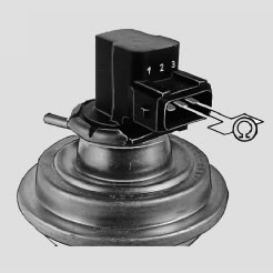
EGR valve with potentiometer feed back
Potentiometer resistance can be checked with the harness
disconnected. Voltage test is preferred with the harness
connected using a suitable scanner / scope or multimeter.
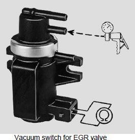
Electro-Pneumatic Vacuum Pump Valve
Using the vacuum pump can verify if the valve is sealed or
leaking when not activated and if the valve opens when the
solenoid is activated. Solenoid resistance can also be
tested with an ohm meter.
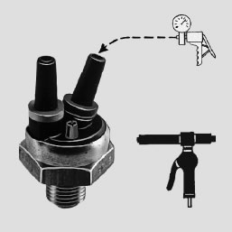
Thermo Valve
Using the vacuum pump can verify if the valve is closed
when cold and heating the unit with a heat gun should
result in the valve opening above approximately 70
degrees Celsius.
2. Electric EGR Valve Test
The combination EGR valve and feedback system in this
unit is controlled and monitored by the ECM and requires
no external vacuum source to operate.
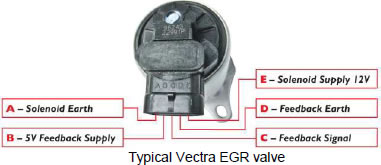
Note: This is a typical vehicle pin out configuration but this
can vary for different vehicle models. Always refer to
correct wiring diagram.
A suitable scanner can assist in testing this type of EGR
valve by using the scanner program to activate the solenoid
and also monitoring the feedback signal. The switching of a
functioning valve can be audible when the engine is not
running.
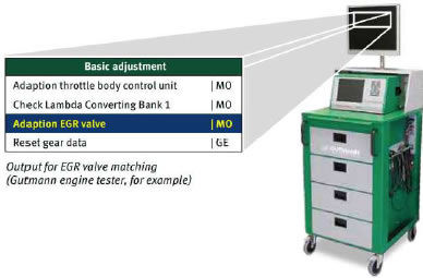
On later vehicles, renewing the EGR valve requires relearning
by using program options in the scanner. That is
the electric EGR valve must be adapted to the ECU.
Tips for troubleshooting EGR – Its Exhausting!
The most common cause of malfunctions in the EGR
systems are stuck or blocked EGR valves due to excess
carbon build up. This generally results in incorrect sealing
between the exhaust and inlet and results in idling
problems and poor performance.
In most cases the EGR valve is replaced but the cause of
the excess carbon is not investigated, why?
Engine Management systems where an Intake Air
Temperature (IAT) sensor is located directly in the inlet
manifold can assist greatly is diagnosing leaking EGR
valves.
That is, monitoring the IAT output signal from a cold start –
idling condition, should not indicate rapid increase in intake
air temperature.
This would be the case if the EGR valve was allowing
exhaust gas to enter the inlet manifold when not required.
|


