|
Latest News
Exhaust Gas Temperature Sensor (EGT)
In the pursuit of better performance and fuel economy manufacturers introduced Direct Injection (GDI) for petrol engines and Common Rail (CRD) for diesel engines. While the original objectives of better fuel economy and performance were achieved an unfortunate consequence of the high combustion temperatures and pressures that this technology relies upon is the formation of harmful Nitrogen Oxides (NOx) and fine particulates in the exhaust emissions. To control the formation of these harmful emissions various strategies are employed. Monitoring the temperature in the exhaust at various locations as an important input to the Engine Control Unit (ECU). The ECU needs this information to be able to control the air-fuel ratio, EGR function and particulate filter regeneration to effectively reduce those harmful emissions.
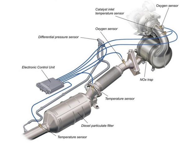
Image source: avidtp.com
The Exhaust Gas Temperature Sensor has a resistor in the tip that changes its resistance when there is a change in temperature. Using a voltage divider circuit in conjunction with the ECU, the EGT input to the ECU will be seen as a voltage that varies according to the temperature of the exhaust. The varying voltage to the ECU may increase or decrease as the temperature increases depending on what type of resistor is in the EGT.
 
Symptoms
A fault in the Exhaust Gas Temperature circuit can be indicated by several symptoms including:
- Loss of performance due to overload of the particulate filter.
- Poor fuel consumption.
- Various warning lamps indicating a fault. (glow plug, particulate filter, ECU)
- An increase in exhaust emissions.
Causes of Failure
The failure of an Exhaust Gas Temperature can be caused by:
- Physical damaged to the sensor or wiring when work on the exhaust is performed.
- Severe vibration.
- Incorrect routing of sensor wires.
- Excessive exhaust temperature (above 900 degrees Celsius) due to incorrect air-fuel ratios or a fault in the engine management system.
- Contamination (oil, coolant etc.).
Diagnostics
A physical inspection of the EGT for damage often reveals damage done to the sensor when exhaust repairs have been performed.
On Car Testing
The EGT circuit can be assessed using a suitable scan tool to extract any fault codes set and to monitor the sensor output in the workshop or on a road test
Typical fault codes may include:
- P2031 Exhaust Gas Temperature Sensor Circuit Bank 1 Sensor 2
- P2032 Exhaust Gas Temperature Sensor Circuit Low Bank 1 Sensor 2
- P2033 Exhaust Gas Temperature Sensor Circuit High Bank 1 Sensor 2
- P2034 Exhaust Gas Temperature Sensor Circuit Bank 2 Sensor 2
- P2035 Exhaust Gas Temperature Sensor Circuit Low Bank 2 Sensor 2
- P2036 Exhaust Gas Temperature Sensor Circuit High Bank 2 Sensor 2
The output voltage of the sensor can also be tested using a digital volt meter. Best checked at the ECU.
Off Car Testing
Exhaust Gas Temperature Sensors can be bench tested using a digital multi meter to measure the change in resistance of the sensor as heat is applied to the sensor using a hot air gun.
Refer to manufactures specifications for testing procedures and specifications.
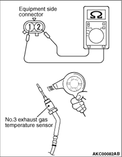
Image source: mitsubishi.automotive-manuals.com
Caution
Ensure that the correct sensor has been fitted to the correct location as they are designed to monitor a specific temperature range depending on their specific location.
The PAT Emission range includes more than 140 Exhaust Gas Temperature Sensors (EGT) from the world’s leading manufacturers, covering over 15 million vehicles on road in Australia and New Zealand.
When you supply and fit products from PAT you can expect a product designed and tested to the vehicle manufacturer’s specifications offering OE Form Fit and Function.

|