|
|
|
|
|
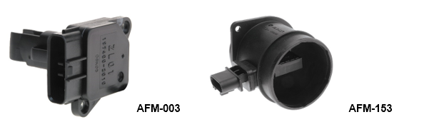
The Mass Air Flow Sensor is located between the Air Filter and Throttle Body. It is a vital component of the Engine Management System and measures the amount of air entering the engine and often includes the Intake Air Temperature Sensor (ATS). The Mass Air Flow Sensor signal (along with other sensor inputs) is used by the Engine Management ECU to determine correct Air/Fuel ratios, Ignition timing and on some vehicles transmission shifting.
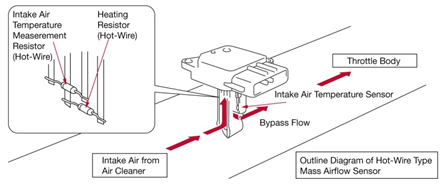
How Does It Measure the air flow Inside the Mass Air Flow Sensor there is a small electrically heated wire or hot wire (heating resistor). A temperature sensor (intake air temperature measurement resistor) is located near the hot wire and measures the temperature around the hot wire.
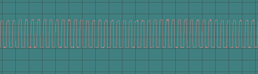
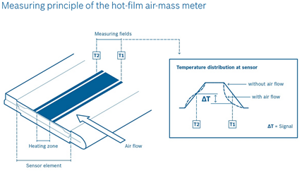
VE Commodore 3.6 l Mass Air Flow Signal at idle. Hot Film Air Mass Meter Hot Film Air Mass Meters calculate the exact air mass flowing in the intake by measuring the difference in temperature of two defined temperature fields. As air flow across the sensor increases, the temperature difference also changes. An integrated electronic module calculates the air mass from the temperature difference and sends this signal to the ECU.
What Goes Wrong Signs that something has gone wrong may include poor general performance, poor idle quality, lack of power, black smoke from the exhaust, poor fuel economy, DTC etc. The major cause of Mass Air Flow Meter (MAF) premature failure is contamination of the hot wire/sensing element. Airborne contaminates passing across the hot wire or sensing element accumulate over time. This contamination may come thru the air filter while the engine is running, oil contamination from oil fumes remaining in the intake manifold or left over EGR residue. This contamination effects the MAF’s ability to accurately determine the air flow. Later model MAF’s changed their design to reduce the effect of airborne contaminates. The amount of air flowing across the sensing element was reduced as well as design changes allowing the heavier contaminant particles to bypass the sensing element. Although this improved the contamination problem it did not eliminate it. Note: The use of reusable oiled air filters that have been over-oiled can often be the cause contamination. Diagnostics MAF signals are best looked at with an appropriate Scan Tool or Oscilloscope at varying engine speeds and compared with a known good signal or manufacturer’s specifications. Diagnostic trouble codes will be set by a faulty or badly contaminated MAF. Typical DTC’s associated with MAF faults include but are not limited to,
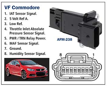
It is important that a technician diagnosing a vehicle for a suspected MAF fault does not forget to check the simple things. Leaks in the air induction system or intake manifold can cause the MAF sensor to give false readings. Faulty wiring and electromagnetic interference from the ignition system can also effect the signal to the ECU. Output voltages and frequency specifications differ depending on application and the type of MAF used. Always refer to manufacturer specifications and procedures. Note: After renewing the MAF, on some vehicles, it may be recommended to perform a MAF sensor learning procedure. Refer to manufacturer specifications and procedures. MAF sensors can range from a simple 3 terminal sensor that monitors air flow only to 8 terminal sensor monitoring air flow, temperature, pressure and humidity.
The PAT Emission range includes more than 340 Air Flow Meters and sensors from the world’s leading manufacturers, covering over 20 million vehicles on road in Australia and New Zealand. When you supply and fit products from PAT you can expect a product designed and tested to the vehicle manufacturer’s specifications offering OE form fit and function.
|
Latest News
Tech Tips - Wheel Speed Sensors (WSS) |


| privacy statement terms of use terms and conditions sitemap news |  |