|
|
|
|
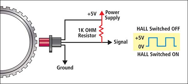
Latest News Diagnosing Crank Angle Sensors (CAS) The required precautions for a Technician to be aware of when diagnosing possible CAS faults on the vehicle. Even though in the previous article on Crank Angle Sensors the purpose, the various locations on the engine, the basic operation of each type and the basic test procedures were covered; more specific CAS information may be required to further assist the technician in any diagnostic or testing process. Further detailed information a Technician may require: When carrying out a Hall CAS “detailed test” using a suitable oscilloscope, the technician “needs to know” the type of CAS characteristic that they are working with to verify the correct expected signal wave pattern “Pull Down” and “Pull Up” Hall effect CAS basic operation. Pull down HALL sensor design.
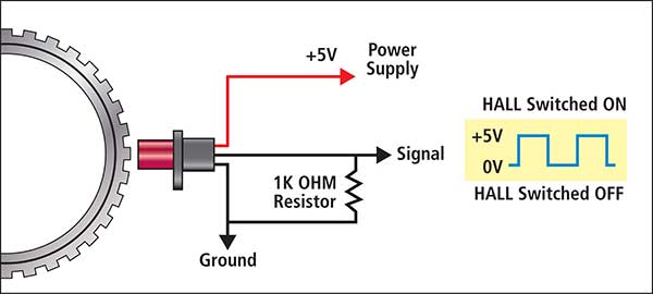
Whilst the HALL Sensor is in the switched off phase, the typical 0 – 5V output during normal operation would indicate the 5V reading of the typical square wave signal. (5V is used as a typical reading – in some cases this may vary). As the Hall sensor is switched “ON” due to the rotating trigger wheel, the output voltage is then pulled down to 0V. This continuous switching completes the typical square wave that would be seen for a typical Hall CAS Signal. The resistor and its location shown in the wiring diagram above ensures some Internal circuit protection, ensures a constant stable 5V as an output and determines the “Pull Down” operation characteristics. Pull Up HALL Sensor design. Relocating the resistor between the signal and the ground now changes the characteristic of the HALL sensor signal output.
Whilst the “Pull Up” type HALL sensor is in the switched off phase, the typical 0 – 5V output during normal operation would indicate the 0V reading of the typical square wave. As the HALL sensor is switched “ON” due to the rotating trigger wheel, the output voltage is then pulled up to 5V. These 2 types of sensor operations must be identified to ensure correct on vehicle diagnosis as well as correct engine operation. For this reason, during replacement the two CAS types cannot be incorrectly substituted. The CAS is a commonly renewed item for many reasons:
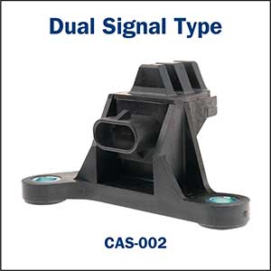
It is important to only fit a quality CAS component to ensure suitable service life and customer satisfaction. In most cases the CAS and trigger mechanism generally create a single “digital or inductive” signal type output as required but there are systems that utilise a dual output signal. Common example of the Dual Signal Type design used on the earlier V6 commodore:
The vehicle utilises a 3X square wave signal as well as a 18X square wave signal for quicker cylinder position and rotation identification to assist in a quicker engine starting condition.
No start if the signals are lost. (the engine will remain running if the 3X signal is lost after engine Start but will not restart once switched OFF). Testing CAS with suitable oscilloscope When an incorrect CAS signal is suspected of being the cause of an engine running malfunction, a suitable oscilloscope is generally utilised to capture or monitor the signal to allow the technician to determine if it is the cause. Prior to any oscilloscope testing, the technician requires to identify the type of CAS that is fitted to the vehicle and a suitable “known good” output signal to be used as a comparison. Typical example of testing a Hall sensor signal on the vehicle: Jeep 4.0ltr (CAS-053)
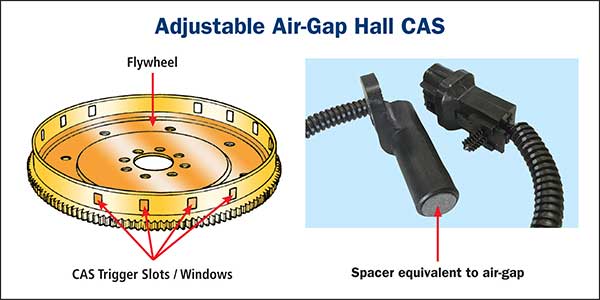
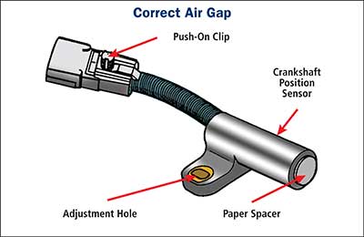
With this type of adjustable Hall sensor CAS with trigger windows located on the drive plate, it is important that the air gap is correct. Contact between the CAS and the drive plate will of course destroy the CAS. A large air gap may alter the output signal to a point where misfiring or hard starting may be the result. The replacement new units are supplied with the correct air gap spacer attached to minimise incorrect installation procedure.
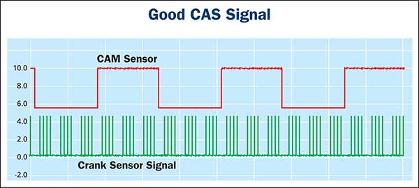
Typical “known good” CAS signal. (for CAS-053 Jeep sensor) Groups of four 5V “pull up” CAS signals that match the trigger windows as expected. Note: CAM sensor signal may be used to ensure the CAM / Crank relationship is correct. An incorrectly phased CAM and Crank sensor may cause multiple problematic engine running characteristics.
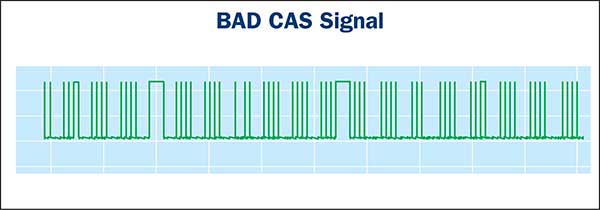
A typical incorrect signal for this type of CAS-053 Jeep sensor:
This CAS signal would cause multiple engine running problems. The air gap (or lack of it) is the first check to be made prior to carrying out further tests. The Premier Auto Trade Sensor range includes more than 360 Crank Angle Sensors (CAS) from the world’s leading manufacturers, covering over 16 million vehicle applications in Australia and NZ. When you supply and fit products from Premier Auto Trade you can expect a product designed and tested to the vehicle manufacturer’s specifications offering OE form, fit and function. Premier Auto Trade distributes products throughout Australia via a network of specialised resellers and leading automotive groups. |
Latest News
Tech Tips - Wheel Speed Sensors (WSS) |
| privacy statement terms of use terms and conditions sitemap news |  |


