|
|
|
|
Latest News MAP Sensors (MAP) What a Technician needs to know about MAP (Manifold Absolute Pressure) sensors when diagnosing related faults and testing operation on the vehicle. “Know what you are working with” The MAP sensor monitors the varying pressure that exists in the intake manifold due to the movement of the throttle valve during all driving conditions. For engines that utilise a MAP sensor, the type of air intake system will determine the MAP sensor operating specifications.
Any engine that can increase the intake manifold pressure above 1 Bar during driving conditions (means of Turbo charger or Super charger or both) will require a MAP sensor that can monitor these higher manifold pressures. (A 1 Bar MAP sensor is not suitable.) Typical Raceworks MAP sensors available for pressures greater than 1 Bar.
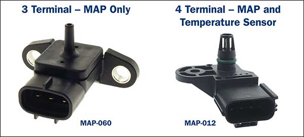
Note: Many MAP sensors may look similar but vary in specification, so it is important to ensure correct unit is fitted. That is - If an engine has been modified by increasing the intake boost system pressure, the MAP sensor specification requirements may also have been altered and would require the suitable MAP sensor for the pressure. For more detailed information on individual Raceworks MAP sensors please refer to individual Data sheets and information on the Raceworks website. MAP Sensor Function/Operation Simplified. Common Analogue Type: Note: The MAP sensor signal may also assist the ECM in the control of the EGR valve on other systems that also utilise a Mass Air Flow unit as well. Digital frequency type: Location of MAP sensor: Many earlier vehicles mounted the MAP sensor onto the firewall and was connected to the intake manifold Via a vacuum hose. This creates a potential build-up of engine oil fumes directly into the integrated MAP sensor and into the ECM. (especially on high kilometre vehicles). Many turbo Petrol and Diesel vehicles utilise a pressure sensor on the intake manifold to assist in EGR control as well as a similar turbo boost sensor generally located on the intake air tract system for turbo pressure control. Note: These may include air temperature sensors to monitor both boost intake air temperature as well as manifold Intake temperature. This type of sensor is identified by an extra connector terminal.
MAP sensor faults. There are many external factors that can cause the MAP sensor output signal to be incorrect which may be mistakenly Typical external factors affecting MAP sensor output voltages:
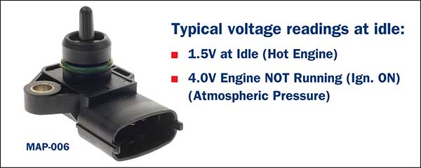
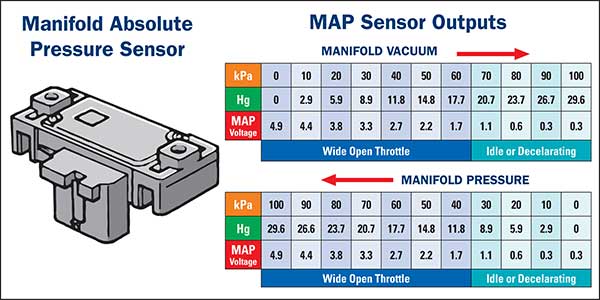
The engine vacuum may be tested with a suitable vacuum gauge and should indicate suitable vacuum for engine type. Typical manifold pressure to MAP sensor “voltage output” relationship example.
General electrical faults. The voltage (or frequency output signals) from the MAP sensor to the ECM must be stable and correctly represent manifold vacuum. Any MAP sensor circuit Earth/Ground as well as reference voltage deficiencies will affect the output signal to the ECM creating incorrect fuel system and ignition system operation. A suitable scanner or oscilloscope can quickly check for MAP sensor output voltages or Frequencies. Typical MAP sensor logged fault codes: P0106 Manifold Absolute Pressure Sensor Performance. Typical vehicle affects due to incorrect MAP signal:
The Premier Auto Trade Sensor range includes over 130 MAP Sensors (MAP) from the world’s leading manufacturers, covering almost 8 million vehicle applications in Australia and NZ. When you supply and fit products from Premier Auto Trade you can expect a product designed and tested to the vehicle manufacturer’s specifications offering OE form, fit and function. Premier Auto Trade distributes products throughout Australia via a network of specialised resellers and leading automotive groups.
|
Latest News
Tech Tips - Wheel Speed Sensors (WSS) |
| privacy statement terms of use terms and conditions sitemap news |  |


