|
|
|
|
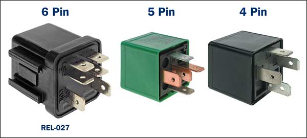
Latest News Relays (REL) What a Technician needs to know when diagnosing and testing various relays types and relay circuits on vehicle systems. The modern vehicle has over the time, increased the number of electrical systems and relays to allow for greater system control by the various Electronic Control modules. (ECM) With these increased electrical loads, it is important that the targeted voltages and currents are supplied to ensure continuous and uninterrupted operation during broad temperature changes and extreme vibrations. Whether it’s the cooling fan circuit, an air conditioning compressor or a starter motor circuit, any relay interruption to an electrical load may cause at least an uncomfortable journey or possibly a trip on a tow truck. In the workshop or during a break down condition, the technician must know the type of relay fitted and its operation to ensure the correct test procedure is carried out. Note: The relays incorporate an activation circuit that will open and close the main power contacts as well as a Power circuit that allows a suitable current to pass through contact set/s to a specific load when activated. (Both these circuits are tested separately on a vehicle.) Types of common automotive relays:
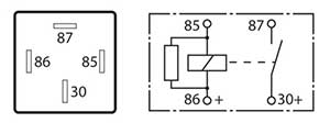
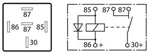
The 4-pin configuration may either be: A normally open (NO) relay. – where the internal mechanical contacts are held open when the relay Is in a disconnected or non-activated state. The contacts close when the relay is activated. This is the most common type found on the vehicle. An Amp rating will generally be indicated on the relay. A similar in resemblance “power relay “is utilised for switching nominal current of 50 Amps or more, making them suitable for starter motors, glow plug operation and motor relay for ABS to name a few.
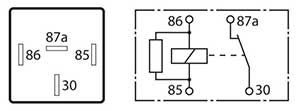
A normally closed (NC) relay – where the internal mechanical contacts are held closed when the relay Is in a disconnected or non-activated state. The contacts open when the relay is activated. An Amp rating will generally be indicated on the relay.
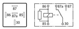
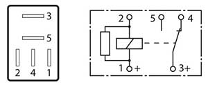
The 5-pin change over relay. Two sets of contacts are utilised on this type of relay where one set is normally open, and the other set is normally closed when the relay is in a disconnected or non-activated state. When activated, the contacts will reverse in operation. This type of relay will generally display two Amp ratings (one for each contact circuit) and it is important that a replacement relay unit Amp rating is suitable for the circuit that it controls.
The 5 pin normally open dual output relay. This type of relay is similar to the 4 pin normally open relay but with an extra output terminal. The contact for both terminals are open when the relay is in a disconnected or non-activated state. The contact closes when the relay is activated and both terminals will be live.
Note: The Amp rating and configuration are not the only criteria for correct relay selection.
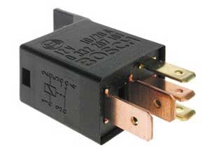
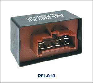
Similar in operation to the Mini relays but due to their size, these units are ideal for space restricted areas. The micro relays also vary in pin configuration to the mini relays but are still available in 4 and 5 pin with similar variations and features. It is important to identify correct terminals for test purposes on these units as the pin identification may vary.
Pin identification may vary to the mini relays as follows:
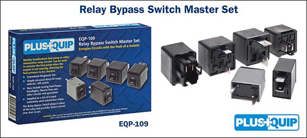
Faults / Diagnosing and Testing. A relay may intermittently fail under certain conditions or fail totally with no circuit function at all. This may be confused with wiring harness or connector faults that can create the same conditions, so it is important to correctly verify the fault. Simple test equipment available can assist in quickly determining the origin of the fault to reduce diagnostic time and valuable time wasted. Typical Simple Test Equipment. PlusQuip EQP-109 Relay Bypass Switch Master Set. Replacing the suspected faulty vehicle relay with a compatible PlusQuip EQP-109 test relay provides direct control of the power circuit. Using the test relay ON / OFF switch can instantly determine if the power circuit is functioning correctly by activating the targeted circuit “load “component. (Pump, Fan motor etc).
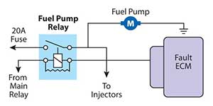
If the targeted “load” functions correctly with the test relay, the technician can then carry out relevant tests on the relay activation circuit. This may include wiring circuits, related switches and possible ECM. Note: A common occurring vehicle fuel system fault is the lack of fuel pump relay winding excitation that can stop the fuel pump operation whilst driving, resulting in an engine stall condition.
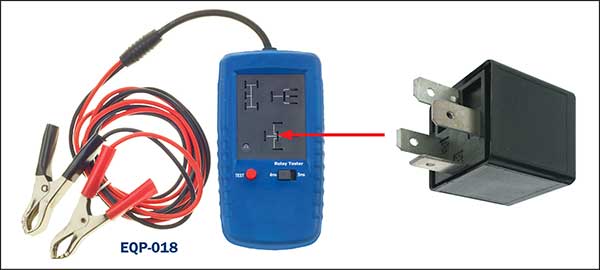
Renewing the relay and sending the vehicle on its way is not a thorough test. The ECM heat level may cause an Interruption in the internal ECM relay activation circuit that will cause the fuel pump circuit to fail. Cooling the ECM generally will again temporarily re activate the fuel pump relay until the ECM heat level rises and fails again. PlusQuip EQP-018 Relay Tester. If the relay is suspected of being faulty, the PlusQuip EQP-018 can quickly verify its operation by a YES/NO light.
There are of course multiple relay combinations on a range of vehicles that require a more detailed understanding of circuit operation as the increased number of terminals will require the technician to refer to manufacturers test procedures and pin out diagrams for assistance.
The Premier Auto Trade Sensor range includes almost 70 Relays (REL) from the world’s leading manufacturers, covering over 2.5 million vehicle applications in Australia and NZ. When you supply and fit products from Premier Auto Trade you can expect a product designed and tested to the vehicle manufacturer’s specifications offering OE form, fit and function. Premier Auto Trade distributes products throughout Australia via a network of specialised resellers and leading automotive groups.
|
Latest News
Tech Tips - Wheel Speed Sensors (WSS) |
|||||||||||||||||
| privacy statement terms of use terms and conditions sitemap news |  |


