Latest News
Cooling Fan Switches (CFS)
What technicians need to know about cooling fan switches (CFS) and their related wiring circuits (used to control the electric cooling fans) when the system malfunctions.
Note: The CFS is generally a thermatic unit that will activate a fan relay by switching ON at a set coolant temperature and deactivate the fan relay by switching OFF at a slightly cooler temperature to prevent any rapid switching (ON /OFF cycle) of the electric fan/s.
With the variety of engine cooling fan systems available on vehicles typically found in regular automotive repair workshops, the system and components operation of these vehicles require total understanding prior to any diagnosis and/or physical testing.
Typical system variations may be:
- Single electric fan utilised for Air Conditioning operation only and activated by the compressor clutch circuit. (no CFS required). Note - Mechanical fan used for general Engine cooling.
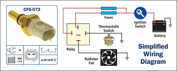
- Single electric fan activated by a thermatic CFS only. The CFS controls the fan relay activation at set coolant temperatures.
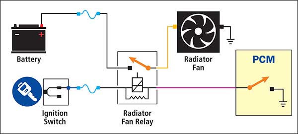
- Single electric fan activated by a fan relay and controlled by the PCM and coolant temperature sensor. (No CFS required on this system.)
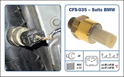
- Single electric fan with low speed and high-speed activation controlled by the 3 terminal dual contact CFS. This allows the high-speed fan function to activate when the air conditioning operates or when engine temperature requires it. Generally mounted on the radiator assembly.
Multi Cooling Fans
Multiple cooling fan systems may utilise CFS units as part of the system operation. Many of these vehicle systems may seem complex and require a clear operating wiring diagram to eliminate confusion. Generally, the CFS operates in conjunction with the Air Conditioning system as well as the Coolant Temp Sensor signal sent to the PCM.
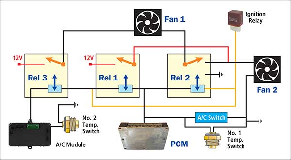
Typical Toyota 2002 -2005 V6 Camry fan control system.
There are two fan motors that may operate at low speed or high speed depending on the cooling system temperature. Operating the fan motors in a series circuit will result in low speed operation. Operating the same fan motors in parallel circuit will result in high speed operation.
There are two separate Temp Switches fitted to this vehicle, with number 1 switch located at the lower radiator tank and the number 2 switch located at the front of the cylinder head. When number 2 switch or the A/C module is switched to Ground, the 2 main fans will operate at low speeds. When number 1 switch or the A/C pressure switch internal contacts close, the 2 main fans will switch to full speed.
Testing this system
If the fans do not function:
- Check both temperature switches operation.
- Ensure all fan relay units function. – Check power supply to relays.
- Ensure fuses are not open circuit.
- Ensure fan motors function. (supply power supply to each fan and inspect).
Note:
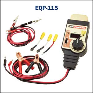
Control modules may generally be utilised to control fan motors on later vehicles. Many of the fan controllers rely on Pulse Width Modulation (PWM) to control the variable fan speed. The use of specialised test equipment for these motors can eliminate the unnecessary and expensive fan motor replacement.
The PlusQuip EQP-115 Electronic EGR / Throttle Body And Actuator Tester is a suitable tester used to drive all PWM controlled actuators/motors.
The Premier Auto Trade Sensor range includes almost 90 Cooling Fan Switches (CFS) from the world’s leading manufacturers, covering almost 2 million vehicle applications in Australia and NZ.
When you supply and fit products from Premier Auto Trade you can expect a product designed and tested to the vehicle manufacturer’s specifications offering OE form, fit and function. Premier Auto Trade distributes products throughout Australia via a network of specialised resellers and leading automotive groups. |


