|
|
|
|
|
Latest News Exhaust Gas Oxygen Sensors Questions for a Technician to think about when an O2 sensor fault code has been logged on a customer’s vehicle. The more information you have, the more accurate the diagnosis.
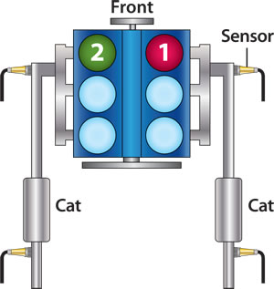
It is important for the technician to identify the targeted sensor to reduce diagnostic time and the incorrect replacement of parts. OBD 11 diagnostic system allows for sensor identification by its location on the exhaust. An example of a typical fault code may be:
This sensor can be quickly identified by using the following: BANK 1 - Indicates exhaust bank that is utilised by Cylinder 1
The odometer reading may quickly identify if the 02 sensor requires renewing if it is the originally fitted unit. These sensors are a service item and must be renewed when required. (Please refer to service book for further info) A recently renewed correct sensor that keeps logging the same related code would generally indicate that there may be external factors that create the conditions to log this continuous fault code. Excessively lean or rich mixtures caused by vacuum leaks and other engine management components have been the cause of multiple misdiagnosed O2 sensor replacements. Utilising the short term and long-term trim function within the Vehicle ECU with a suitable scanner can assist the technician with quick and accurate diagnostics. Note: Understanding Fuel Trim The fuel trim system is used to maintain as close as possible the ideal 14.7: 1 air/fuel ratio to ensure suitable combustion. Three-way catalytic converters need the mixture to be constantly driven rich/lean at this ratio to work efficiently. Fuel trims can compensate for other vehicle issues which makes fuel trims so useful. Typically, an intake vacuum leak that creates a lean mixture at low throttle conditions causes the trim system to Increase the fuel for combustion to maintain the correct mixture. This is indicated on the scanner as a positive percentage figure. The greater the vacuum leak, the greater the amount of fuel that would be required. Example: a combined short term and long term trim indication of “+18“ would indicate an increase of 18% of fuel supplied for combustion. The fault would need to be rectified to minimise trim compensation. Alternatively, if a combined trim figure was negative (example “-22”) this would indicate that the fuel quantity has been reduced by 22% to maintain correct mixture. Again, this cause requires correction to minimise trim compensation. Excessive positive or negative trims may cause the O2 sensor to function outside of its range and log a fault code.
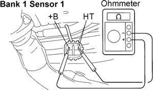
O2 /AFR Sensor Heater Circuit resistance check.
All 3,4 and 5 wire O2 and Air Fuel Ratio sensors incorporate an integrated heater circuit to raise the sensor temperature quickly. Any causes of heater malfunction will generally result in a heater malfunction fault code. Checking O2 sensor heater resistance with an Ohmmeter will quickly identify for any open circuits. These resistance readings generally vary between vehicle models, so it is important that the correct sensor is fitted. Note: Generally, very low heater resistance circuits (readings of approx. 0.8 – 3.0 Ohms) are controlled by the ECU by pulsing the heater Earth circuit. High heater resistance circuits (readings of approx. 8.0 to 16.0 Ohms) generally have the heater Earthed directly to the chassis. It is also important that the O2 sensor power supply for the heater circuit has been tested to ensure it meets specifications.
Testing an O2 sensor or Air Fuel Ratio sensor may be carried out using a suitable scanner/scope but It is important that you identify which sensor you are dealing with as the sensor workings and testing procedures vary dramatically.
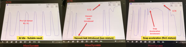
Pre-Cat O2 sensor. (Oscillates between approx. 0.2 V – 0.8V) Typical Pre-Cat graph images taken on 3.6ltr VF Commodore at Idle
Oscillating voltage signals can assist the technician in determining the oxygen content prior to the catalytic converter under various operating conditions. This information with the assistance of the short and long-term trims can generally identify any possible areas to further investigate if required.
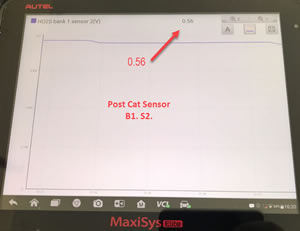
Post Cat O2 sensors. The Post – cat sensor signal varies to the Pre-Cat sensor as shown below.
If the Post cat sensor signal was nearly identical to the Pre – Cat sensor, the catalytic converter would need to be possibly replaced and further investigated.
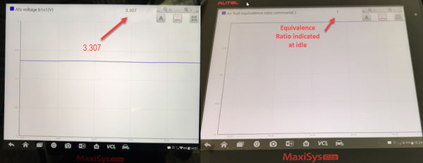
A Scanner indicated voltage represents the targeted 14.7:1 air fuel ratio or Stoichiometric indicated voltage at idle. This value will vary depending on vehicle. Example: Toyota Corolla (below) indicates a 3.3V Stoich reading.
A Subaru may indicate a Stoich reading of 2.2V. To verify the correct indicated voltage for the vehicle being tested, refer to the Equivalence Ratio on the scanner which should indicate a figure of “1”. Any variations to this value (1) would indicate a lean or rich condition and would also indicate an incorrect Stoich reading and should be investigated. Effects on readings when mixtures are altered.
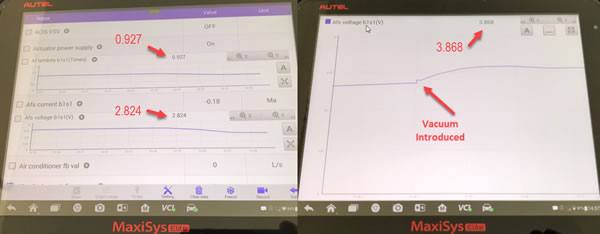
A steady indicated Stoich voltage should alter at idle if a lean or rich mixture was introduced. By snap accelerating or introducing extra fuel, monitor the scanner screen and a “drop” in voltage should be evident whilst the mixture is richer. Refer image above indicating a “reduced” voltage of 2.824V during snap acceleration.
Again, the voltage should return to its correct Stoich value when the vacuum leak has been repaired and the correct mixture is achieved. Note: It is important to fit the correct sensor to the vehicle and the VIN may be required to ensure this. The Premier Auto Trade Emissions range includes over 800 Oxygen Sensor and Air/Fuel Ratio Sensors, from the worlds leading manufacturers including Walker Products, NTK, Bosch, Denso and more. When you supply and fit products from Premier Auto Trade you can expect a product designed and tested to the vehicle manufacturer’s specifications offering OE form, fit and function. Premier Auto Trade distributes products throughout Australia via a network of specialised resellers and leading automotive groups.
|
Latest News
Tech Tips - Wheel Speed Sensors (WSS) |


| privacy statement terms of use terms and conditions sitemap news |  |