|
|
|
|
Latest News Testing Electric Valve Solenoids (EVS) What technicians need to know when carrying out diagnosis or testing on an EVS unit or related circuit fault. As mentioned in the previous EVS article these units are fitted to multiple control systems in the modern vehicle and may be known as:
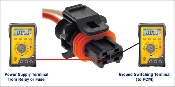
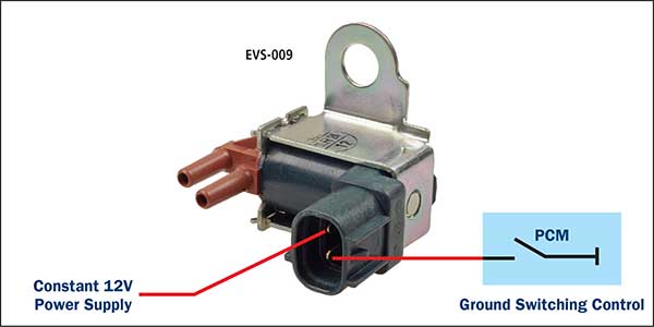
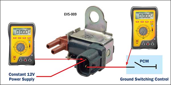
There are of course multiple causes of failure in the specific systems that the technician is required to investigate, but before any tests can be carried out, the method of switching control of the EVS is necessary so the correct testing procedure can be performed on the unit and related circuit. Please refer to previous article as above for EVS types and mechanical operation. Typical common EVS switching circuit. Ground switching control in PCM. (Ground side switched – most common) Depending on the system circuit, a constant Battery power supply is generally directed to one of the EVS terminals. The other EVS terminal is connected to the PCM where it is (control) grounded. Checking the voltage at the harness terminals with the connector disconnected, can quickly identify the specific EVS terminals.
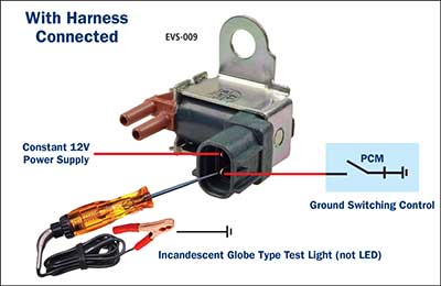
For other tests reconnect the harness connector.
To determine the type of circuit and/or to carry out an electrical test procedure:
Possible alternative voltage results caused by faults in the EVS or circuit:
Note: If “no EVS pulse” is evident during an activation request, the use of a conventional incandescent type test light may be used to activate the EVS circuit. Contacting the ground control terminal should result in an audible activation sound. If an audible sound is evident then further tests are required at the PCM area to determine the cause for no PCM switching. (test light is acting as a safe ground for the circuit switching).
Note: A typical normal operating current through an EVS is approx. 0.370 Amps. A conventional (incandescent) type test light operating current is approx. 0.186 Amps and is quite acceptable for a test tool for this purpose as it allows sufficient current to activate the EVS. An LED test light is not suitable to activate the EVS as there is insufficient current flow through the LED assembly and can only be used for signal monitoring. Typical vacuum flow circuit test method for EVS. Note: it is important to ensure all vacuum hoses are connected correctly/ tightly fitted and not leaking prior to any vacuum related EVS fault tests. Typical faults may be intermittent or hard fault:
Note: The open or closed conditions may be due to electrical faults or unit internally jammed. It is important to ensure the actuator and related system mechanism is functioning correctly to prevent misdiagnosis.
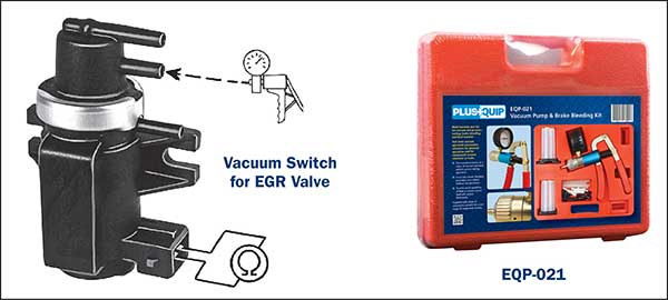
Electro-Pneumatic Vacuum pump valve Using the vacuum pump can verily if the valve is sealed or leaking when not activated and if the valve opens when the solenoid is activated. Solenoid resistance can also be tested with an ohm meter. The Premier Auto Trade Emission range includes more than 40 Electric Valve Solenoids (EVS) from the world’s leading manufacturers, covering over 2.7 million vehicle applications in Australia and NZ. When you supply and fit products from Premier Auto Trade you can expect a product designed and tested to the vehicle manufacturer’s specifications offering OE form, fit and function. Premier Auto Trade distributes products throughout Australia via a network of specialised resellers and leading automotive groups.
|
Latest News
Tech Tips - Wheel Speed Sensors (WSS) |
| privacy statement terms of use terms and conditions sitemap news |  |


