|
|
|
|
|
Latest News Ignition Modules (MOD) What Technicians need to know about Ignition module types, precautions, operation and testing. We all know that the purpose of the ignition module (a switching device) is to interrupt the current flow through the primary circuit of the Ignition coil to induce a high-tension spark for cylinder combustion. Even though the auto industry generally labels all switching devises as “modules”, there are many variations that must be identified by the technician due to different test procedures utilised to ensure correct operation. Typically: Ignition modules, Igniters, power transistors, DFI modules, TFI modules etc. This refers to distributor type and distributor less type ignition systems. Note: Distributor type systems may utilise a distributor mounted mechanical ignition vacuum advance mechanism, or the advance may be controlled electronically by the module and associated circuits. Typical examples of Ignition coil switching device purposes and their location.
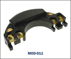
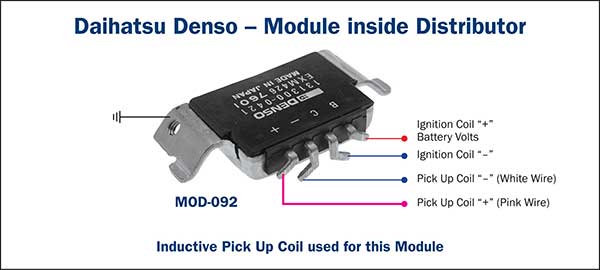
This module utilises a directly connected inductive pick up coil and the reluctor for switching command. Positive and Negative ignition coil terminals are directly connected to this module.
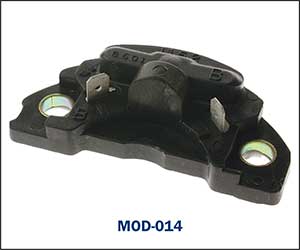
This module utilises a directly connected inductive pick up coil and the reluctor for switching command.
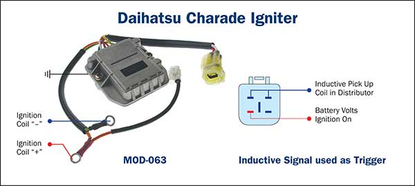
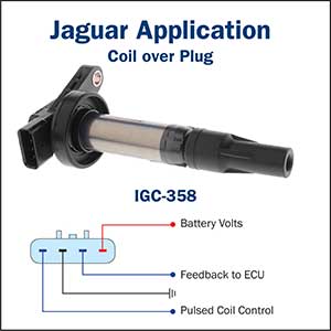
The inductive pick up coil signals are directed to the ECU for processing prior to the switching command being carried out by the ECU at IGT terminal which includes timing control.
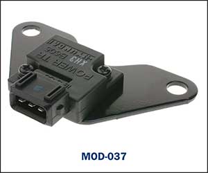
This module and pick up coil assembly directly connects to the ignition coil.
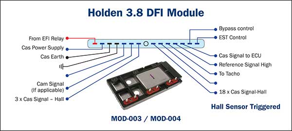
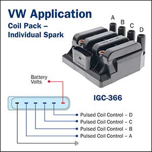
Three waste spark ignition coils are directly operated by this module with digital (Hall type) crank angle sensor signals utilised for timing control in conjunction with the PCM.
The ECU switching demand is amplified by the power transistor to directly operate the ignition coil. The ignition timing is calculated and controlled by the ECU.
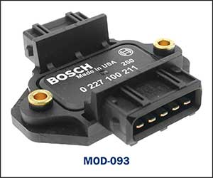
The ECU switching demands are amplified by the power transistors to directly operate each ignition coil. A 4-cylinder example is shown. (2 units fitted for 8-cylinder application) Ignition timing is controlled by the ECU.
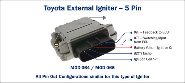
The igniter amplifies the ECU switching demand to operate the internally mounted distributor ignition coil. Ignition timing is controlled by the ECU and associated circuits.
The igniter amplifies the ECU switching demands to operate the ignition coils as required. Ignition timing is controlled by the ECU and associated circuits.
Each Ignition coil igniter amplifies the ECU switching commands to operate the ignition coil as required. Ignition timing is controlled by the ECU and associated circuits. Important precautions to be aware of when working with Ignition modules.
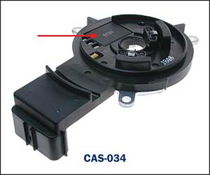
Note: The correct pickup coil polarity utilised by the ignition module is essential for correct operation. Reversing the pickup coil polarity will result in extreme ignition timing inconsistencies. Typical example:
If the pink and white wires were reversed soldered on the module – the ignition timing would alter by approx. 20 degrees. Testing the ignition modules will vary depending on the type fitted. A suitable oscilloscope can assist with the testing of voltage signals to the module and also the output to the ignition coils. The Premier Auto Trade Ignition range includes more than 108 Ignition Modules (MOD), covering over 1.6 Million vehicle applications in Australia and NZ. When you supply and fit products from Premier Auto Trade you can expect a product designed and tested to the vehicle manufacturer’s specifications offering OE form, fit and function. Premier Auto Trade distributes products throughout Australia via a network of specialised resellers and leading automotive groups. |
Latest News
Tech Tips - Wheel Speed Sensors (WSS) |


| privacy statement terms of use terms and conditions sitemap news |  |